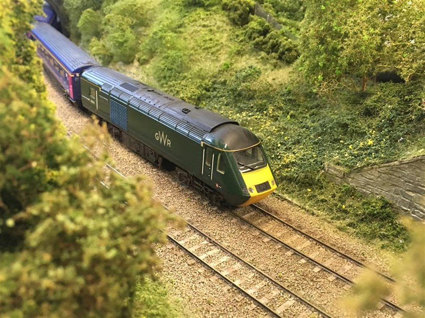
We are pleased to introduce the first 3D printable magnetic NEM couplings for the Hornby HST / Mk3 / Mk3SD NEM rolling stock. The only coupling on the market today that is always in stock and available instantly! Unlike other magnetic couplings, these couplings are designed to be automatically uncoupled without the 'Hand of God'.
Available now:
In this article, we will:
- Introduce you to the Trackside3D couplings
- Show you how to 3D print them on a Creality Ender 3
- Look at different magnet options
- Show you how to install the magnets
- Explain some of the Key Features
- Look at the specially designed Mk3SD coupling
- Suggested upgrades for the Ender 3 (optional)
- Automatic Uncoupling
- Whats next?
The cost in materials (PLA plus magnets) to produce 10 pairs of couplings is approximately £1.28, about one tenth the cost of other retail product packs which typically sell for around £12.95. The digital download to produce the coupling costs less than £2, you only need to buy the download once and can produce unlimited prints for personal use.
What you will need to print these are:
- Filament 3D Printer (such as the Creality Ender 3) [£215]
- Roll of black PLA (or PETG) [£18]
- Pack of 3mm (diameter) x 4mm (height) cylinder magnets [~£6]
- Trackside3D HST Slam Door NEM coupling pack [£1.99]
Some of the advantages with the Trackside 3D couplings:
- Unlimited printing for personal use
- FREE Lifetime Design Updates
- Designed and tested for specific rolling stock
- Your choice of magnets
- Both axial and diametric magnets are supported
- Use Axial magnets for North or South couplings
- Use Diametric magnets for no polarity couplings
- Rotate Diametric magnets for stronger north/south couplings
- Break one, just quickly reprint replacements and swap magnets
- Always in-stock
- Instant delivery (no shipping, no delays)
- More prototypical looking (modeled on real Mk3 coupling)
- Prototypical coupling action and sound
- Designed for automatic uncoupling
- Come in NEM adjustable and fixed lengths
- Couplings "float" using the magnetic field enabling close coupling on tighter curves
Trackside3D provide FREE Lifetime updates. If the 3D printing technology improves, if Trackside3D tweaks the design or correct an unforeseen design problem, the updated object files are available to everyone who has purchased the design. The system will send you an email alerting you to the availability of an updated design. This doesn't cover new variants or new designs based on an existing product.
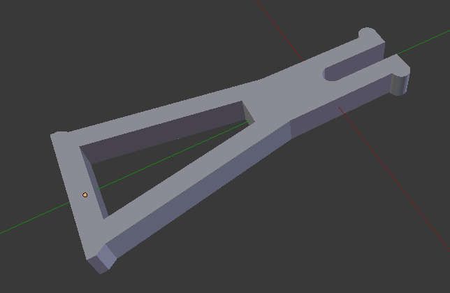
Introducing the Trackside3D Couplings
Check back for our upcoming YouTube video, or subscribe to our YouTube channel at https://youtube.com/oorail to make sure you get a front row seat and never miss any of our cool model railway innovations!
You can download the couplings from Trackside3D:
How to print the couplings on an Ender 3
The couplings are printed with the Trackside3D small object settings, along with the following changes:
- Heated Bed Temperature should be 68C
- Nozzle Temperature should be 218C
- Black filament (PLA recommended)
- Brim should be enabled
- Print speed should be reduced to 10mm/sec
- Brim print speed should be at 20mm/sec
- Travel speed can be left as-is (adjust if needed)
- Supports enabled (for HST stepped coupling and Mk3SD)
- Support settings should be tri-hexagon
- Enable retraction between layer changes
Here are the Cura settings we used to successfully print the couplings on the Creality Ender 3, Ender 5 and CR-10:
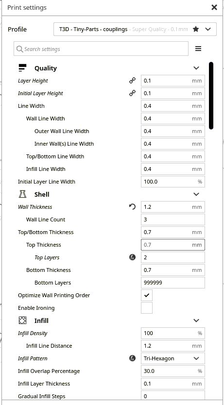
The infill density of 100% produces a stronger coupling, given the small size and delicate nature of the NEM dove tail, I wouldn't recommend adjusting this to save a tiny amount of plastic filament. Likewise the Tri-Hexagon pattern has worked well for us in testing.
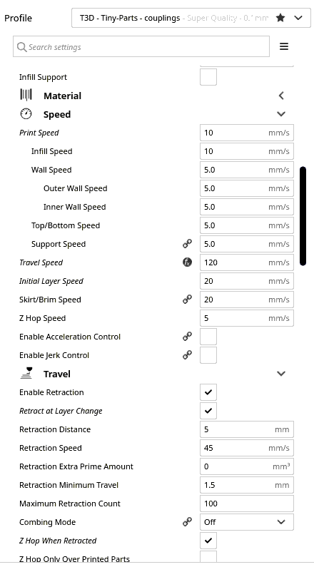
The print speed of 10mm/s and initial layer speed are critical parts to a successful print. Keeping the travel speed at 120 mm/sec is important as due to the small area the nozzle is working in, you want it to move away to another area quickly. Retraction is also important, especially during layer change. This will prevent the print from being distorted with too much heat due to the proximity of the nozzle.
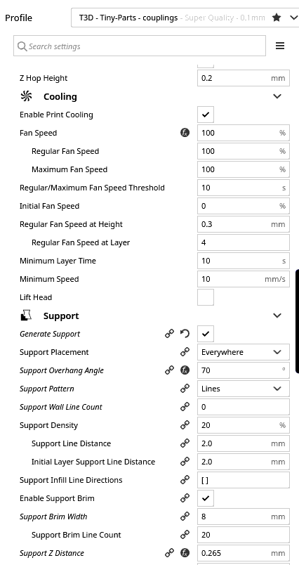
Supports are necessary for our HST power car couplings because the coupling head is elevated, as the 3D printer cannot print in thin area for very long distances, you need to enable supports. Since most modellers will only need two HST power car couplings per set, I would recommend printing the two HST power car couplings in a single print job with supports enabled, and then print the HST Mk3 Slam-door couplings in a separate print job with supports disabled.
For a successful print, I would recommend copying the support settings EXACTLY as they are shown above and below. You could potentially play around with the Support Pattern and Density (could stand to be reduced a few percentage points). Adjusting the support density and Support Z distance will make the supports easier (or more difficult if you adjust them the other way) to remove from the print. If you are having difficulty cleanly removing the supports from the print, you should look into adjusting this.
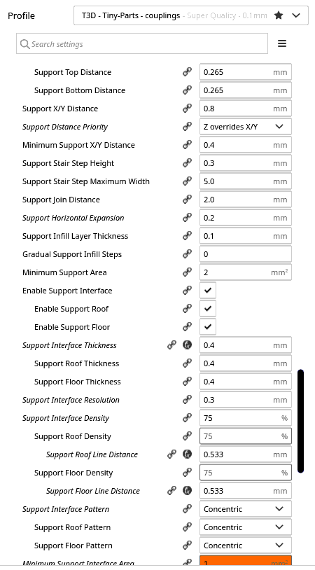
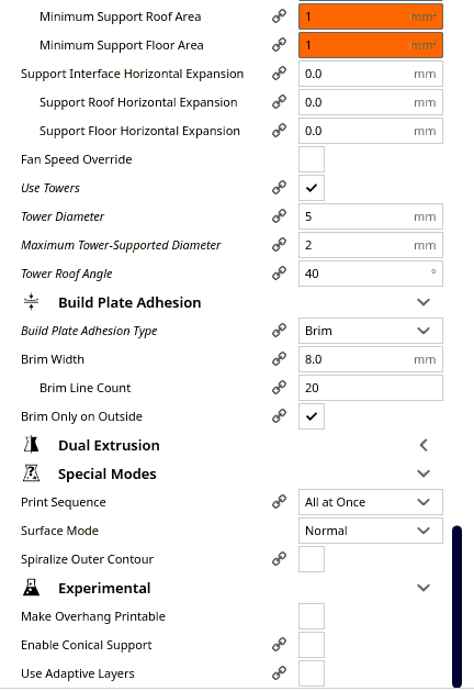
You can safely ignore the warnings (orange) in Cura, it will print just fine with these settings. For the Build Plate Adhesion, we recommend using Brim due to the small size of the prints. The Brim helps keep the small print stuck to the print surface for the entire length of the print. We had consistent print problems (mostly prints lifting from the print surface) with skirt or no adhesion type. If you are looking to reduce post-print cleanup, I would recommend reducing the width and/or brim line count.
We used Hatchbox3D Black PLA, Overture3D Black PLA and Proto-Pasta HTPLA when testing the couplings.
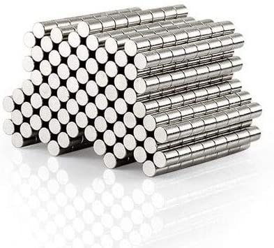
Choosing your magnets
These HST Mk3 / Mk3SD couplings are designed to work with cylinder magnets with a diameter of 3mm or 1/8". The optimal size of magnet is 3mm, but 1/8" is 3.175mm, so the design can accommodate 1/8" magnets.
The optimal magnet height (thickness) for the design is 4mm, however the design will work with magnets between 2mm and 6mm in height. It will also work with two 3mm x 2mm magnets. For magnets available in imperial, we recommend magnets up to 3/16" in height (4.76mm).
Cylinder magnets are available in two different types, Axial and Diametric. Axial magnets have the N/S pole split across the center axis, so the top half of the magnet is North, and the bottom half is South. Diametric magnets have the poles split across the diameter. So the left hand side of the magnet is North and the right hand side of the magnet is South.
When choosing a magnet for a coupling there are three things to consider:
- Magnet Strength (long, heavy trains, inclines, tight curves etc)
- Polarity or Non-polarity (restricted or unrestricted coupling options)
- Automatic Uncoupling (important for shunting etc)
Depending which combination of these are important to you, will determine the type of magnet you will want to buy for your 3D printed couplings.
If you plan to pull long heavy trains around tight curves or long inclines, then you will want to consider stronger neodynium magnets. These magnets are slightly more expensive than your standard ferrite fridge magnets, and considerably stronger. They are available in a variety of sizes and strengths, more common ones are N35, N42 and N52. The trade-off with a more powerful magnet is that it makes automatic uncoupling more challenging due to the strength of the magnetic fields involved.
Polarity basically means you have one coupling with the North pole facing outwards, and another coupling with the South pole facing outwards. They are attracted to each other, as opposite poles attract. However this approach restricts coupling arrangements, you will not be able to connect a North pole coupling to another North pole coupling.
To get around this problem you need to either use two magnets side by side with opposite poles, or a single magnet installed sideways so that both the North and South poles are facing outwards. For our couplings, this means using a different type of magnet:
| Coupling Type | Magnet Type | Polarity / Non-Polarity |
|---|---|---|
| HST Power Car Standard | Axial | Polarity |
| HST Power Car Standard | Diametric | Both |
| HST Mk3 Standard | Axial | Polarity |
| HST Mk3 Standard | Diametric | Both |
| HST Power Car Slide Door | Axial | Non-Polarity |
| HST Power Car Slide Door | Diametric | Polarity |
| HST Mk3 Slide Door | Axial | Non-Polarity |
| HST Mk3 Slide Door | Diametric | Polarity |
From the table above you can see that its possible to support polarity, non-polarity and even both by carefully selecting a different style of magnet.
It should be noted that depending on the magnet, if you are using both poles facing outwards for non-polarity, you may have a slightly weaker connection than if you had the north and south poles head on, however in most cases this should be negligible.
Our approach to automatic uncoupling requires a fine balance between the strength of the magnetic field between the couplings and the automatic uncoupler. If the magnetic field between the couplings is too strong, perhaps you went all out with a powerful N52 magnet, then automatic uncoupling becomes more challenging, as you need a larger opposing magnetic field to uncouple. For rolling stock where the NEM pocket is attached to the bogie, too much opposing force will result in derailment.
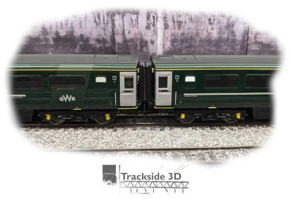
In testing we had a lot of success using much cheaper "Amazon" fridge magnets with the uncoupler. This worked very well with freight rolling stock and our GWR Mk3 slam door (standard) sets, even up to 8 coaches. Simple options such as a stronger neodymium bar magnet placed in the baseboard under the track, and adjusting the train speed over the top of the magnet to decouple, worked well. More complex options such as offsetting magnets on opposing sides and electromagnets with sensors, also had good results.
This solution requires a fine balance, a weaker magnetic field between couplings makes automatic uncoupling a lot easier. The trade-off though is you could end up with random uncoupling on inclines or if you decide to add too many coaches to a rake. A magnet-coupling combination that works fine for one type of coach might not work for another set as well.
A good example of this are the Scotrail Mk3SD coaches, these worked fine being pushed (power car at the end) with the same "fridge" magnets we tested out on the GWR Mk3 Slam Door coaches. However, when being pulled we noticed the magnets would occasionally run into problems traversing a set of Hornby curved points. They ran perfectly on other sections of the layout. Swapping out the magnets for stronger N42 cylinder magnets instantly solved the problem, but required some adjustments to the automatic uncoupler in order to get it to work properly again. Using N35, or a stronger ferrite magnet, neither of which I had on hand, probably would have resulted in better results.
If you want to do automatic uncoupling, we highly recommend starting off with weaker magnets, such as those fridge / craft magnets you can buy on Amazon. You want to find "Just Enough Magnet" for what you want to couple up, which involves finding the weakest magnet that works. This involves starting off with a weak magnet, and swapping it out with stronger ones until you find ones that work. If you find the fridge / craft magnets just don't work for you, start with the lowest possible neodymium magnet you can find, most likely N35.
The magnets we used were sourced from K&J Magnetics and Amazon, however there are plenty of on-line suppliers in the UK and across Europe that can also supply you with magnets. The magnets we used from K&J Magnetics are as follows:
| Magnet Shape | Diameter | Thickness | Strength | Magnetized | Part Number |
|---|---|---|---|---|---|
| Cylinder | 1/8" (3.175mm) | 3/16" (4.76mm) | N42 | Axial | D23 |
| Cylinder | 1/8" (3.175mm) | 1/4" (6.35mm) | N42 | Axial | D24 |
| Cylinder | 1/8" (3.175mm) | 1/4" (6.35mm) | N42 | Diametric | D24DIA |
| Cylinder | 1/8" (3.175mm) | 1/8" (3.175mm) | N42 | Axial | D22 |
| Cylinder | 1/8" (3.175mm) | 1/8" (3.175mm) | N52 | Axial | D22-N52 |
How to install the magnets
The magnets are easy to install:
- Remove the brim from the print by hand
- Use a knife / sharp edge to strip excess plastic from the part
- Use a knife to open the prongs on the NEM dovetail (if necessary)
- Use a small file to clean up any excess plastic on the part
- Repeat 1-4 for the coupling cap (Mk3 standard only)
- Use a small flat screwdriver to insert the 3mm x 4mm magnet
- Place the coupling cap over the top of the magnet
- Optionally glue the coupling cap with Tamiya Extra Thin Cement Glue (Mk3 standard only)
For the Mk3SD couplings, we recommend using axial magnets and make them all exactly the same way. For ours, we place the south pole in first. This will enable non-polarity operation and makes it very easy to create the couplings.
If you are assembling a lot of couplings, we recommend using a reference magnet (with a known N/S pole) or print a pair of reference couplings that you don't use. We suggest marking either the north or south couplings with a silver or white permanent marker at the end of the dovetail. That way, you can easily identify the couplings. We have produced a NEM height tool which can accommodate a 1/8" or 3mm block (cube) magnet. This can be used to create reference magnets. You can also just print out a spare coupling and install a magnet in it as a reference magnet.
The Mk3 standard couplings must be of opposite polarity to work if you are using axial magnets, so one coupling must have the North pole on top, and South pole on the bottom. The other coupling must have the South pole on top and the North pole on the bottom. For convenience, we recommend putting a North/South coupling on one end, and South/North coupling on the other.
In the Mk3 standard couplings, diametric magnets will work as both non-polarity couplings and polarity couplings. To use the diametric magnets as a non-polarity coupling, simply align the open area of the coupling so that both the North and South poles are exposed in the opening. To use the diametric magnets as a polarity coupling, simply make sure only one pole is exposed in the opening. This is achieved by rotating the magnet. In most cases, you will likely want to glue the diametric magnet in place once you have it orientated the way you want it to prevent it from moving due to magnetic forces. The coupling is designed to hold the magnet in place without gluing, we recommend gluing the coupling cap in place and only gluing the magnet if you run into problems.
Key Features of the new couplings (Slam Door)
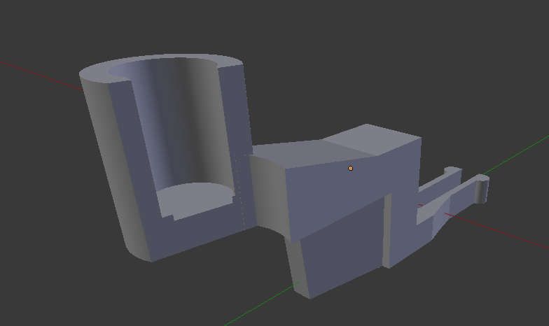
Both the HST Power Car and Mk3 Coach couplings feature an optimized NEM dovetail design. The design features fraction of a mm narrower dovetail with a wider gap between the tails which facilitates easy installation.
The wider design towards the outside edge of the NEM pocket which slopes inwards results in a snug connection with the NEM pocket without the risk of damaging the pocket or the coupling.
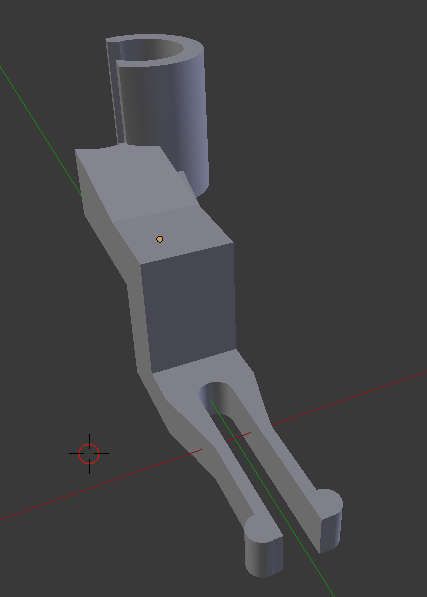
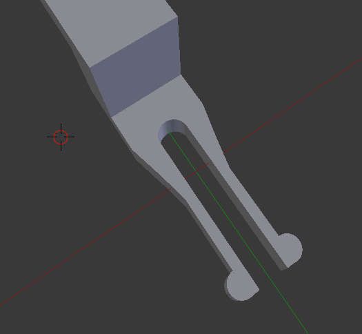
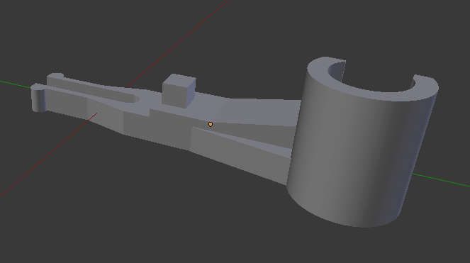
The HST power car couplings are stepped as the NEM pocket is low on the power cars compared to the Mk3 coaches. The Trackside3D HST coupling has a reinforced edge, not only does this add stability and strengthen the coupling for smoother operation, it also minimizes the amount of support material needed when 3D printing, resulting in an easier to remove and stronger coupling.
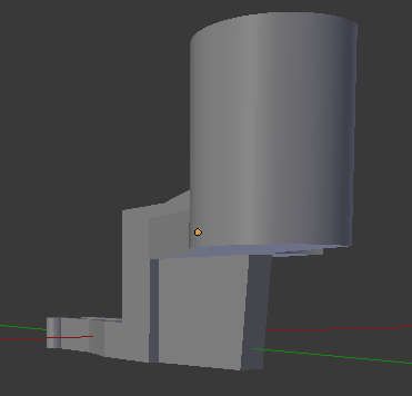
The 3mm (diameter) x 4mm (height) cylinder magnet is secured in a casing that maximizes the surface area between the magnets while securing the magnet. The design allows the magnet to slightly "float" when coupled enabling bogie movement (e.g. GWR Mk3 Slam Door) around tight curves. The design can accommodate 1/8" diameter cylinder magnets.
The couplings are designed with an angled arm on one side and the magnet casing is angled to produce a more prototypical coupling motion when the magnets are in close proximity. The couplings approach at a slight angle, then the magnetic force gently clamps them together. There is no violent smashing together of rolling stock like some retail magnetic couplings with oversized magnets.
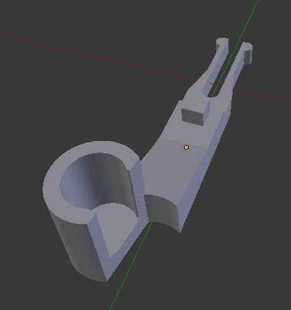
The mirror-image couplings are angled in such a way that they are balanced. The magnetic field and the angle of the coupling help to produce a more realistic motion when the train is moving. The couplings are notched slightly so that the couplings interlock in place with the force of the magnet.
The Mk3 coach couplings come in a number of fixed lengths for different levels of close coupling. An adjustable version without the NEM block allows you to control the distance between coaches by adjusting how much of the NEM dovetail is inserted into the NEM pocket.
The coupling cap is a small circular piece of plastic that is inserted above the magnet into the coupling. This can be glued in place to secure the magnet further. It will also make the magnet less visible. The coupling caps come in a variety of heights which result in either a recessed, flush or slightly protruding circle on the top of the magnet.
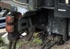
For reference, here is an image of a real Mk3 coach coupling (aka. a buckeye coupling):
A modified design for the Mk3 Slide Door Rolling Stock
The new Mk3SD rolling stock (GWR, ScotRail, Cross Country) use a completely different design to attach the NEM pocket to the passenger stock. The new Mk3SD coaches have a NEM pocket attached to the body shell that slides inside a channel, which reduces the clearance between the NEM pocket and the body. The new coaches have additional detailing parts, including a small buckeye coupler. This required a modification to the coupling design. (Note: We are currently testing a version of our original design that is slightly lower for the Mk3SD, this will be available in a few days).
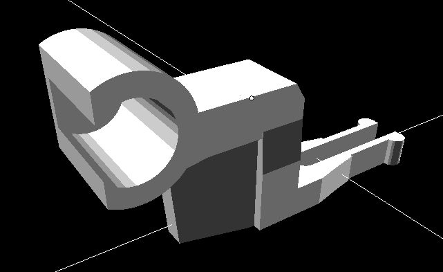
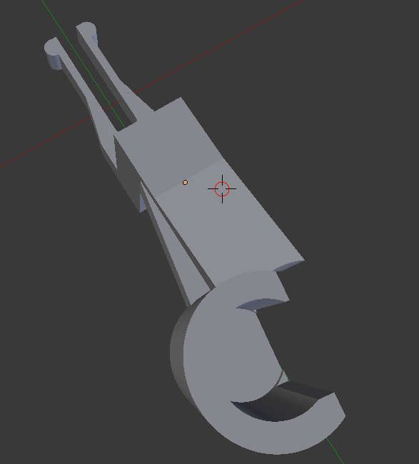
The Mk3SD couplings are very similar to the Mk3 couplings. The cylinder shaped coupling head is rotated 90 degrees and slightly offset for a balanced coupling. The coupling head faces straight-on instead of at an angle. The couplings are shorter as there is no overlap between the couplings.
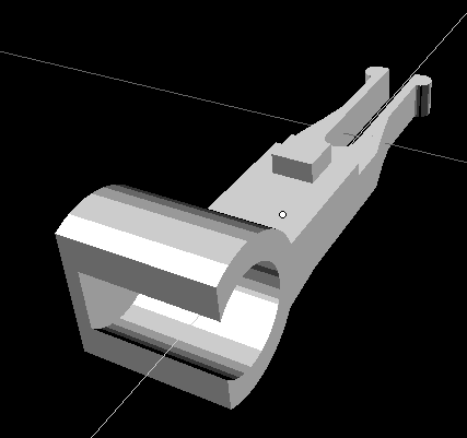
The Mk3SD coupling has the cylinder coupling head rotated 90 degrees. The cylinder is slightly offset for balance and is slightly closed more than the standard Mk3 coupler. This is to prevent very strong 3mm magnets from being pulled out of the coupling head. The coupling is slightly shorter and narrower than the Mk3 coupler for slam door coaches. As the magnet attaches straight on, there is no need for the arm in this design.
Suggested upgrades to the Ender 3
These upgrades are not necessary for successful prints, however with these upgrades we have noticed a 100% success rate at printing high volumes of couplings and other small items on the Ender. We recommend making the following upgrades to your Ender 3 to make it easier to print very small parts at slow speeds:
- Replace the Bowden tubing with Capricorn Tubing
- Replace the Extruder with a Dual-Gear Metal Extruder
- Replace the Print Bed with a Magnetic Print Bed
- Replace the nozzle with a hardened steel nozzle
- Replace the pneumatic fittings
Automatic Uncoupling
The couplings are designed to support automatic uncoupling. We are currently testing a computer controlled uncoupling system.
With axial magnets, the standard Mk3 couplings have either a North pole or a South pole on the bottom, the opposite coupling will have the opposite pole on the bottom (unless you are using a diametric magnet for no polarity operation). The automatic uncoupling works by "capturing" the trailing coach or wagon while the train moves slowly across the capturing magnet. The capturing magnet has a slightly greater magnetic field, as the couplings pass over the capturing magnet, the trailing coupling will lower slightly as it is captured by the capturing magnet. As the train pulls away, the trailing coach remains in place, while the leading coach is repelled (opposite pole) and continues to move forward with the train. Moving over the capturing magnet with sufficient speed will prevent the coupling from being captured. This is why having "Just Enough Magnet" is critical to uncoupling with this method.
For non-polarity couplings, such as the Mk3SD or the Mk3 with a diametric magnet installed. Placing a capturing magnet of opposite polarity on either side of the track in the uncoupling zone will enable you to uncouple different rolling stock by changing the direction of travel over the uncoupler. This requires some degree of experimentation as the distance to track, height and strength of the capturing magnets will vary from layout to layout.
Alternatively, you can uncouple the rolling stock with a magnetic wand. However, we feel that wands are no less desirable for operation than the "Hand of God".
In our initial testing we used a neodymium magnet attached to a small screwdriver. This was placed near one coupling close to the end of the NEM dovetail, this causes the coupling to slightly disengage, then applying power to pull the locomotive away will complete the decoupling process.
We are currently testing a number of designs that support uncoupling with a diametric magnet installed in the coupler and a computer controlled system. Subscribe to our channel and the Trackside3D mailing list to be the first to learn of the latest developments...
Also Available...
Trackside3D have also released:
- Mk3SD (Slide Door) Coupling Pack
- Small Freight Coupling Pack (Release 7/27/2020)
- Coupling Tools
Whats next?
Here is a quick look at some of the things Trackside3D have in development, these products are currently in testing and expected to be available for download between now and September 30th.
- Non-NEM HST Mk3 couplers (we have a ton of these coaches)
- Oxford Rail Mk3A version
- Slam-door T3D-041-000 (same design) for the Mk3SD
- HST/Mk3 variants for larger sized cylinder magnets
- Designs supporting Ring, Disc and Block magnets
- Mk1 / Mk2 coach couplings
- LNER Teak coach couplings
- Three new upcoming design variants
- Variants for older rolling stock (Hornby Railways, Tri-ang, Lima)
- Multi-magnet version (smaller magnets)
- Loco specific variants
- Automatic uncoupler system
- More videos
If there is something specific you are looking for, please complete the form available here.
The oorail project has been testing these magnetic couplings for many months without any issues on a wide range of rolling stock from new releases to Tri-ang. The oorail project is converting all of its stock to use these couplings, so expect an extensive range of couplings tailored and tested by our engineering team, specifically for exact models over the coming weeks and months.
!!! Shed / Loft Temperature Warning !!!
If you plan to leave your rolling stock or any 3D printed items in a loft or shed that gets extremely hot (e.g. no insulation, no air conditioning), then we highly recommend that you use HTPLA or PETG, such as the HTPLA from Proto-Pasta or any of the popular PETG filaments.
HTPLA is High Temperature PLA, this filament is designed for creating 3D printed objects that you might leave in a hot car in the extreme heat of places like Queensland, Arizona, New Mexico or Dubai. While PLA should be perfectly fine for most conditions, using HTPLA or a good quality PETG will guarantee that 3D printed couplings will not soften in high temperature situations in a loft or shed.
Please note: If you are using PETG or HTPLA, you will need to adjust the recommended temperature settings above based on the recommendation from the material manufacturer. We recommend using the upper-end of the recommended temperature scale. When printing PETG, we typically print it around 238 - 242C with a bed temperature between 65 and 80 C.
Thank Mike
These couplings wouldn't exist without the inspirational modelling work done by Mike Buick with his own prototype magnetic couplings. Mike's Facebook posts last Autumn encouraged us to look into magnetic couplings, design and push the limits of filament 3D printing to create the couplings. We have deliberately priced the coupling downloads at a very low price (under £2.00 for unlimited personal prints) to help make purchasing your own 3D printer more affordable. If you find our couplings useful and have saved yourself some funds, we ask that you consider donating to Meningitis Research to give back to Mike for his inspirational work.
Previous Articles
Interested in how we designed the couplings? Have a look at our previous articles:
Comments